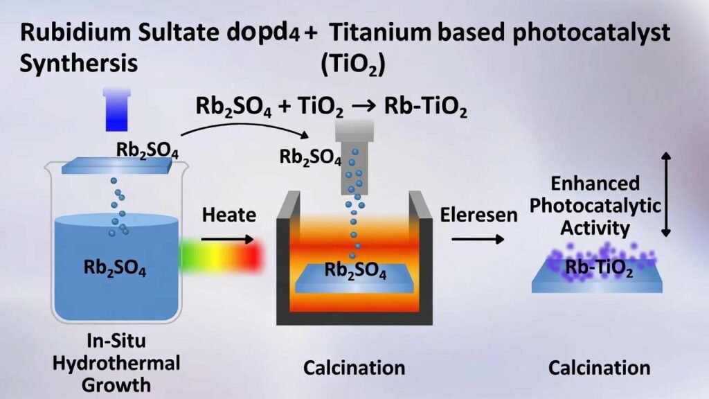
Rubidium Sulfate (Rb2SO4) Doped Titanium-Based TiO2 Thin-Film Photocatalyst: In-Situ Hydrothermal Growth + Calcination
Keywords: rubidium sulfate doping, TiO2 thin film photocatalyst, hydrothermal synthesis, dye wastewater treatment, methyl orange degradation
1) Overview
Textile and dyeing wastewater often contains complex organic dyes that are difficult to remove by conventional methods. Titanium dioxide (TiO2) is widely used as an n-type semiconductor photocatalyst because it is stable, recyclable, low-toxicity, and cost-effective. However, standard TiO2 mainly responds to ultraviolet light due to its wide bandgap, which limits performance under visible light.
This page summarizes a practical preparation route for a rubidium sulfate (Rb2SO4) modified titanium-based TiO2 thin film. The approach grows an oxide film directly on a titanium sheet via in-situ hydrothermal synthesis, then densifies and activates the film through controlled calcination. By introducing Rb+ (metal dopant) and S-containing species (non-metal dopant) from rubidium sulfate, the film morphology and charge behavior are improved, enabling faster pollutant mass transfer to active sites and higher photocatalytic degradation efficiency for organic dyes.
2) Detailed Preparation Workflow (Step-by-Step) + Process Summary
Materials & reagents (typical)
- Titanium sheets (cut to a consistent size; a common lab size is 3 cm × 1.5 cm).
- Nitric acid solution: HNO3 at 0.2 mol/L (prepared using H2O2 as described in the source process).
- Rubidium sulfate: Rb2SO4 at 0.02–0.04 mol/L (key raw material for Rb + S introduction).
- Oxalic acid dihydrate: C2H2O4·2H2O at 0.4–0.7 mol/L.
- Deionized water for ultrasonic cleaning.
Safety note: HF (hydrofluoric acid) and pressurized hydrothermal equipment require strict safety controls, trained personnel, proper PPE, ventilation, and compliant waste handling.
Step 1 — Titanium sheet polishing (surface activation)
- Mechanical polishing: sand the titanium sheet sequentially using 600, 800, 1000, and 1200 grit sandpaper to remove oxide and scratches.
- Chemical polishing: immerse the polished sheet in a polishing solution with volume ratio V(HF):V(HNO3) = 1:10 for 60 seconds.
- Ultrasonic cleaning: rinse and ultrasonically clean the sheet in deionized water multiple times until the surface is free of residue.
Purpose: a clean, activated titanium surface improves nucleation and adhesion of the in-situ grown TiO2 film.
Step 2 — Hydrothermal in-situ growth (Rb2SO4 introduced here)
- Prepare the mixed precursor solution in a Teflon-lined autoclave insert:
- HNO3: 0.2 mol/L
- Rb2SO4: 0.02–0.04 mol/L
- C2H2O4·2H2O: 0.4–0.7 mol/L
- Load the cleaned titanium sheet into the insert, ensuring it is fully contacted by the solution.
- Hydrothermal reaction: seal the reactor and run at 80–200°C for the chosen duration. A commonly used preferred condition is 80°C for 24 hours.
Why rubidium sulfate matters in this step: Rb2SO4 is the controlled source of Rb+ (metal dopant) and S-containing species (non-metal dopant), directly influencing film formation and micro-structure during in-situ growth.
Step 3 — Natural cooling & air drying (film stabilization before calcination)
- After the hydrothermal run, allow the reactor to cool naturally to room temperature.
- Remove the titanium sheet and air-dry at room temperature to obtain a titanium sheet with a grown oxide film (a yellow-toned film can appear prior to calcination in typical runs).
Step 4 — Calcination (density, phase optimization, stronger photocatalysis)
- Place the dried sheet into a muffle furnace.
- Calcine at 400–600°C for 1.0–2.5 hours.
- A widely used preferred setting is 450°C for 1 hour.
Calcination improves film density and stability, enhances charge separation, and helps form a more active TiO2 phase (commonly anatase-dominant), which supports higher photocatalytic efficiency and better reusability.
Example process window (for morphology tuning)
| Condition | Hydrothermal temperature | Hydrothermal time | Calcination (typical) | Notes on evaluation (dye degradation) |
|---|---|---|---|---|
| Option A (preferred baseline) | 80°C | 24 h | 450°C × 1 h | Used as a reference condition; film densification after calcination supports repeatable degradation performance. |
| Option B | 120°C | 30 h | 450°C × 1.5 h | Adjusts film morphology; performance can be benchmarked using methyl orange solutions under UV/partial visible light. |
| Option C | 160°C | 48 h | 450°C × 2 h | Longer growth time often changes microsphere/needle-like structures, impacting surface area and kinetics. |
| Option D | 200°C | 72 h | 450°C × 2.5 h | Extended growth window for morphology exploration; compare activity vs. baseline and unmodified TiO2. |
Typical test setup referenced in the source process: methyl orange at 20 mg/L, 80 W high-pressure mercury lamp (UV + partial visible), with performance assessed by absorbance change after irradiation (e.g., 5 h), and optional synergy testing with small H2O2 addition.
Process summary (what you obtain)
- A titanium-supported TiO2 thin film grown by in-situ hydrothermal synthesis.
- Rb and S co-doping introduced via rubidium sulfate (Rb2SO4), enabling structural and electronic modification.
- A film surface that can include microsphere-based architecture with additional nano-features, improving effective surface area and mass transfer.
- After calcination, a denser, more stable film that is less prone to detachment and supports repeated use.
3) Why Rubidium Sulfate (Rb2SO4) and This Method Deliver Practical Advantages
A. Rubidium sulfate is a high-leverage dopant raw material (Rb + S in one input)
- Dual-function source: Rb2SO4 provides Rb+ (metal dopant) and S-containing species (non-metal dopant) simultaneously, supporting co-doping without complicated precursor systems.
- Micro-dose, macro impact: even low Rb+ levels can strongly influence oxide film formation and the development of microsphere-like structures, improving active site accessibility.
- Improved light utilization: S incorporation can introduce visible-light response (reported red-shift behavior), helping TiO2 move beyond UV-only activity.
- Better charge behavior: Rb-related modification supports electron–hole separation and longer carrier lifetime, which directly translates into higher photocatalytic efficiency.
B. Thin-film architecture beats powder handling in real wastewater systems
- No powder agglomeration: the active layer is a film on titanium, reducing clustering issues typical of particulate photocatalysts.
- Easy recovery & reuse: the catalyst is a solid sheet—simple to retrieve from reactors and suitable for repeated cycles.
- Low catalyst loss: calcination densifies the film, improving adhesion and reducing shedding into water (lower secondary contamination risk).
- Higher effective area: microsphere/needle-like surface features can increase surface area and accelerate pollutant mass transfer to reactive sites.
C. Scalable process controls (ideal for consistent production)
- Clear concentration windows: Rb2SO4 dosing can be controlled by molarity (0.02–0.04 mol/L) for repeatability.
- Simple unit operations: polishing → hydrothermal growth → drying → calcination (no complex coating equipment required).
- Optimization-ready: morphology and performance can be tuned by hydrothermal time/temperature and calcination profile.
- Synergy with advanced oxidation: in UV + H2O2 systems, the film catalyst can further accelerate dye degradation via complementary oxidative pathways.
Rubidium Sulfate Supply Note (for photocatalyst & materials labs)
For stable hydrothermal dosing and reproducible film growth, choose high-purity Rb2SO4 with controlled impurities (e.g., low Na/K, low chloride, low insolubles) and consistent dissolution behavior. Packaging can be matched to lab or pilot scale use.
Disclaimer: The workflow above is a technical process summary intended for materials R&D context. Always follow local regulations, equipment manuals, and SDS/ESHS requirements (especially for HF handling and pressurized hydrothermal operations).Compiled from patent document CN201610570332.2, with all copyrights reserved to the original rights holder.