Rubidium Iodide (RbI)–Enabled High-Speed Blade Coating for Scalable Perovskite Solar Cells in Humid Air
Audience: R&D and Process Engineers | Focus: RbI as a critical iodide salt raw material within mixed-cation perovskite precursor engineering for fast, scalable coating
1) Overview and Technical Value
Perovskite solar cells (PSCs) are attractive for next-generation photovoltaics because they can be made by solution processing, potentially lowering capex and enabling large-area manufacturing. A core scale-up bottleneck is forming uniform, dense perovskite films over larger substrates without sacrificing device performance or stability—especially when moving from small-area lab spin coating to scalable coating methods.
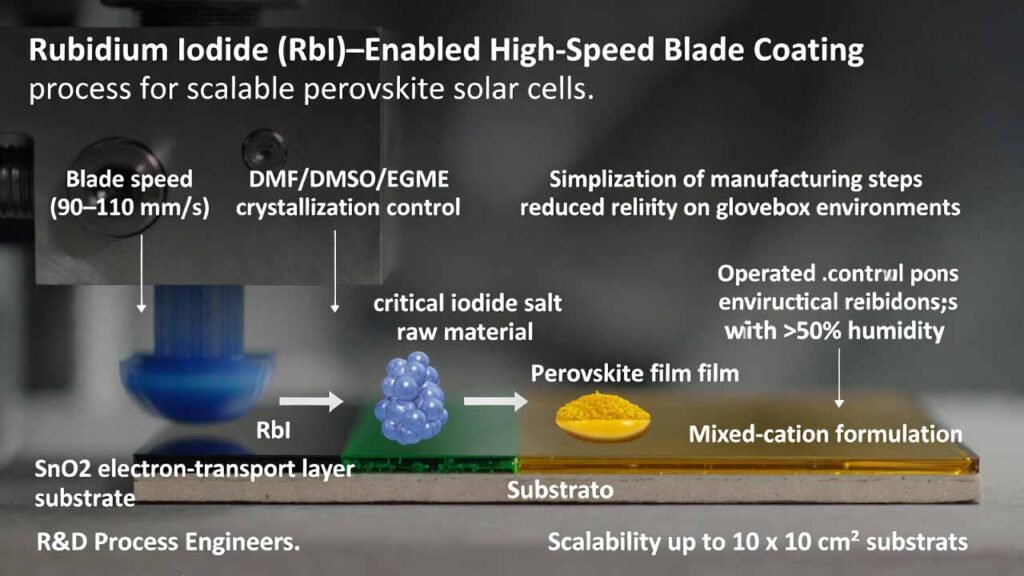
This workflow targets high-speed blade coating (90–110 mm/s) to form a perovskite absorber on an SnO2 electron-transport layer, under indoor air with >50% humidity. The technical value comes from combining:
- Scalable deposition (blade coating) suitable for larger substrates (up to 10 × 10 cm2).
- Solvent engineering (DMF/DMSO/EGME) to widen the crystallization window at high coating speed.
- Mixed-cation iodide formulation including rubidium iodide (RbI) and cesium iodide (CsI) to help stabilize the perovskite phase and support robust film formation in practical humidity conditions.
- Process simplification toward ambient-air manufacturing (reduced dependence on inert glovebox steps).
In this formulation, RbI is used as an inorganic iodide salt raw material (0.0025 mol/L) within the perovskite precursor to tune A-site composition alongside FA/MA/Cs, supporting dense films and stable devices under fast coating.
2) Detailed Experimental Procedure
Process Environment
- Carry out the full device process indoors in air at relative humidity > 50%.
- Substrate options: ITO conductive glass, typical size range 2 × 2.5 cm2 to 10 × 10 cm2.
Step A — Substrate Cleaning and Surface Activation
- Ultrasonic clean the substrate sequentially:
- Tap-water + glass-cleaner mixture (volume ratio 3:1) for 15 min
- Tap water for 15 min
- Anhydrous ethanol for 15 min
- Dry with a nitrogen dust-blowing gun.
- UV–ozone treatment for 30 min to improve surface wettability and reduce organic residues.
Step B — Electron Transport Layer (ETL) Deposition (SnO₂)
- Prepare an SnO2 dispersion by mixing SnO2 powder with anhydrous methanol.
- Set SnO2 concentration to 5–7% (recommended target: 6%).
- Spin coat the SnO2 solution onto the treated substrate.
- Anneal to form a compact ETL (use your established SnO2 anneal profile compatible with ITO and downstream perovskite processing).
Step C — Perovskite Precursor Formulation (RbI-Containing Mixed-Cation Iodide System)
Dissolve the following solids into a mixed solvent of DMF (N,N-dimethylformamide) + DMSO (dimethyl sulfoxide) + EGME (2-methoxyethanol / ethylene glycol monomethyl ether) to obtain the perovskite precursor solution:
| Component | Role in Formulation | Target Concentration |
|---|---|---|
| PbI2 (Lead iodide) | Primary metal halide framework source | 1.0 mol/L |
| FAI (Formamidinium iodide) | A-site cation for bandgap/performance balance | 0.75 mol/L |
| MAI (Methylammonium iodide) | A-site cation to tune crystallization and film formation | 0.20 mol/L |
| MACl (Methylammonium chloride) | Additive for crystallization control and film quality | 0.15 mol/L |
| CsI (Cesium iodide) | Inorganic A-site cation for phase stabilization | 0.005 mol/L |
| RbI (Rubidium iodide) | Inorganic iodide salt raw material for A-site composition tuning and stability support | 0.0025 mol/L |
| L-α-Phosphatidylcholine | Interfacial / film-forming additive | 0.0004 mol/L |
| PEACl (Phenethylammonium chloride) | Passivation / additive engineering for defect suppression | 0.0004 mol/L |
- Stir at room temperature for 14 hours to fully dissolve and equilibrate the precursor.
- Set DMSO fraction in the precursor solvent system to 7–13% (recommended target: 10%) to extend the crystallization window during fast coating.
Step D — Preheat and High-Speed Blade Coating of Perovskite Layer
- Preheat the SnO2-coated substrate on a hotplate at 150°C for 20 s.
- Set blade/doctor-blade parameters:
- Blade-to-substrate gap: 200–300 μm (recommended target: 250 μm)
- Coating speed: 90–110 mm/s (recommended target: 100 mm/s)
- Blade coat (scrape coat) the perovskite precursor onto the SnO2 ETL to form a wet film.
- Post-deposition anneal at 100°C for 5–10 min to crystallize the perovskite layer.
Step E — Hole Transport Layer (HTL) and Electrode Formation
- Spin coat the HTL (example: Spiro-OMeTAD) on the perovskite layer.
- Define electrode deposition regions (e.g., mechanically clear areas as needed for contact).
- Thermally evaporate Ag to form the top electrode:
- Ag thickness: 100 nm
- Example single-device active area: 0.08 cm2
Key Process Window Summary (for quick transfer to SOP)
| Module | Critical Settings |
|---|---|
| Cleaning + activation | 15 min ultrasound each (cleaner mix / water / ethanol) + N2 dry + UV–ozone 30 min |
| ETL (SnO₂) | SnO₂ in methanol; 5–7% (target 6%); spin coat + anneal |
| Precursor solvents | DMF/DMSO/EGME; DMSO 7–13% (target 10%); stir 14 h |
| Blade coating | Gap 200–300 μm (target 250 μm); speed 90–110 mm/s (target 100 mm/s) |
| Perovskite crystallization | Preheat substrate 150°C 20 s; anneal 100°C 5–10 min |
| Ambient condition | Indoor air, humidity > 50% |
3) Comparison vs. Traditional Methods (Summary)
Traditional high-efficiency PSCs are commonly made by spin coating in laboratory settings, often on very small areas. Spin coating spreads solution via centrifugal force, which becomes increasingly non-uniform as area increases, and typically wastes material. In contrast, this workflow uses blade coating, which is more compatible with scalable, large-area manufacturing.
| Dimension | Conventional Spin Coating | High-Speed Blade Coating (This Workflow) |
|---|---|---|
| Scalability / area | Best on small substrates; uniformity drops as area increases | Designed for larger substrates (up to 10 × 10 cm2) |
| Material utilization | Low (significant waste during spinning) | Higher utilization (solution is metered and spread by blade) |
| Throughput | Limited for large-area lines | High-speed coating: 90–110 mm/s supports higher throughput |
| Ambient manufacturability | Often relies on inert atmosphere to control moisture/oxygen | Operates in air at >50% humidity using preheating + solvent engineering |
| Film formation control | Heavily dependent on spin dynamics and antisolvent strategies | Relies on blade gap, speed, substrate preheat, and DMF/DMSO/EGME crystallization control |
Relative to many blade/printed PSC approaches that operate at <50 mm/s, this workflow emphasizes a faster coating regime while maintaining film quality through coordinated solvent/additive design (including RbI).
4) Why Rubidium Iodide (RbI) Matters Here: Practical Advantages in This Application
In high-speed blade coating—especially under humid air—film formation and phase stability must be resilient to fast solvent loss, moisture exposure, and reduced process margin. Rubidium iodide (RbI) plays an enabling role as a raw material in the mixed-cation perovskite precursor:
- A-site composition tuning for stability: RbI introduces a small fraction of inorganic Rb+ into the A-site cation pool (FA/MA/Cs/Rb), which helps the mixed-cation perovskite maintain a more stable crystal landscape during rapid crystallization.
- Defect and non-ideal phase suppression (via formulation synergy): In this recipe, RbI works alongside CsI, MACl, and organic additives (phosphatidylcholine, PEACl) to support denser films and reduce sensitivity to humidity-driven defects during ambient processing.
- Compatibility with scalable iodide-based perovskites: RbI integrates naturally into iodide-rich precursor systems built around PbI2 and iodide salts, preserving strong absorption while improving processing robustness.
- Supports the high-speed window: At 90–110 mm/s, the film is prone to flow instabilities and discontinuities. The mixed-cation iodide chemistry including RbI helps stabilize nucleation/growth behavior when paired with the DMF/DMSO/EGME solvent system and substrate preheating.
RbI Implementation Notes (Engineering-Focused)
- Use RbI at the stated low concentration (0.0025 mol/L) to avoid over-perturbing crystallization while still benefiting mixed-cation stabilization.
- Keep the DMSO fraction (7–13%, target 10%) and the preheat step (150°C, 20 s) consistent—RbI performs best when the overall crystallization window is well-controlled.
- For scale-up, lock down the trio of blade speed + blade gap + substrate temperature first, then fine-tune RbI/CsI ratios and additive levels to match your target thickness, drying profile, and humidity variability.
The mentioned synthesis method references patent document number CN202211460659.6