Cesium Fluoride (CsF) & Rubidium Fluoride (RbF) Supported Catalysts for Hexafluoropropene Dimerization (HFPD) in Fluorochemical Manufacturing
1) Overview and Technical Value
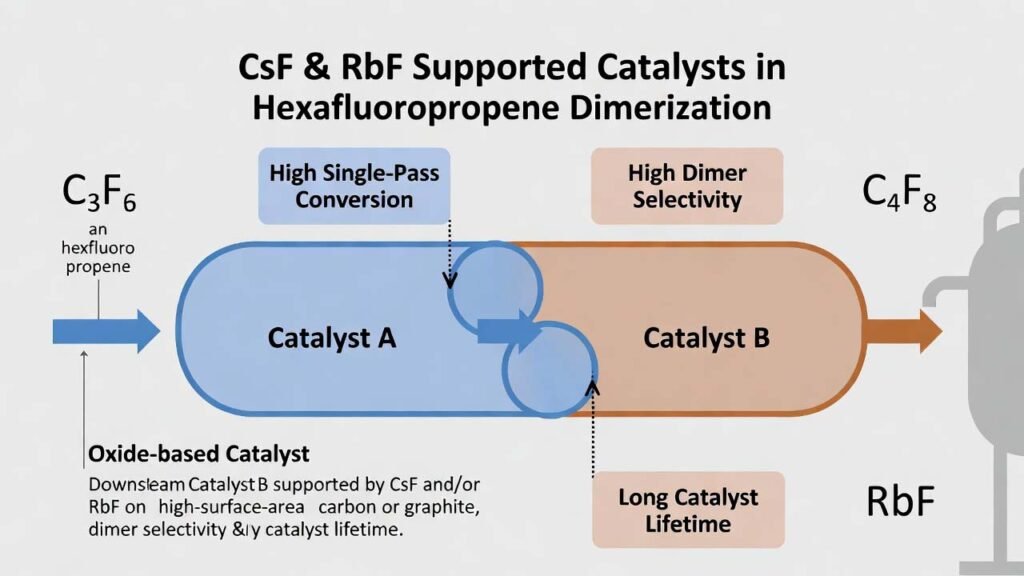
Hexafluoropropene dimer (HFPD) is a key fluorochemical intermediate because the remaining C=C bond enables downstream synthesis of multiple fluorinated derivatives used in pharmaceuticals, fluorosurfactants, specialty solvents, and replacement agents in fire protection chemistries. The practical challenge in HFP dimerization is achieving high single-pass conversion, high dimer selectivity (suppressing trimer formation), and long catalyst lifetime under controllable industrial conditions.
This process uses a two-bed, two-function catalyst system in one tubular reactor: an upstream oxide-based catalyst (Catalyst A) that promotes selective conversion early in the reaction path, followed by a downstream fluoride-salt-supported catalyst (Catalyst B) that drives the remaining conversion while maintaining selectivity. The key differentiator is that CsF and/or RbF are the primary active fluoride salts in Catalyst B, supported on high-surface-area carbon/graphite to create a robust, high-activity fluorination/basic-site environment for efficient dimerization.
2) Detailed Experimental Procedure
Catalyst system architecture
| Catalyst A (upper bed) |
Support A: activated alumina and/or fluorinated alumina (surface-fluorinated Al2O3) Main active oxides: NiO, MgO, MnOx, CaO (one or more) Promoter oxides: ZrO2, PrOx, NdOx, LaOx, CeO2 (one or more) |
| Catalyst B (lower bed) |
Support B: activated carbon and/or graphite Main active fluorides: CsF and/or RbF Promoter fluorides: CuF2, KF, and/or FeF3 |
2.1 Recommended composition windows (for formulation and scale-up)
- Catalyst A: main oxide : promoter oxide (wt) = 1 : 0.05–0.5
- Catalyst B: (CsF and/or RbF) : promoter fluoride (wt) = 1 : 0.05–0.5
- Support loading (A or B): support : (total active + promoter) (wt) = 1 : 0.01–0.6
- Bed mass ratio: Catalyst A : Catalyst B (wt) = 1 : 0.5–3
- Support surface area targets: A = 50–600 m²/g; B = 50–1600 m²/g
- Pore volume targets: A = 0.1–0.65 mL/g; B = 0.1–0.85 mL/g
2.2 Catalyst A preparation (precipitation on alumina / fluorinated alumina)
- Prepare precursor solution (Mix A): Dissolve water-soluble salts of the selected main active metals and promoter metals in deionized water. Add a small amount of nitric acid as needed to aid dissolution and maintain a uniform solution.
- Impregnation / mixing: Add Support A (activated alumina and/or fluorinated alumina) into Mix A and stir to form a uniform slurry.
- Controlled precipitation: Add a basic solution (commonly aqueous ammonia) to the slurry to precipitate metal species onto/within the support.
- Solid-liquid separation: Filter the precipitated solids and wash as needed (standard deionized water practice) to remove residual soluble ions.
- Drying: Dry at 100–130°C for 8–12 hours.
- Calcination: Calcine under nitrogen atmosphere at 400–500°C for 6–12 hours to form the oxide active phases and stabilize dispersion.
2.3 Catalyst B preparation (CsF/RbF fluoride salts supported on carbon/graphite)
- Prepare fluoride solution/suspension (Mix B): Dissolve CsF and/or RbF in deionized water. Add the chosen promoter fluoride (CuF2, KF, and/or FeF3). Add a small amount of nitric acid if required to improve wetting and dispersion.
- Support addition: Add Support B (activated carbon and/or graphite) to Mix B under continuous stirring to ensure uniform contact and uptake.
- Evaporation to dryness: Heat the slurry (commonly around 110–120°C) while stirring until water is fully evaporated, leaving a salt-loaded solid.
- Drying: Dry at 100–130°C for 8–12 hours.
- Calcination: Calcine at 500–550°C for 2–5 hours to anchor the CsF/RbF fluoride phases and improve mechanical/thermal stability of the supported catalyst.
2.4 Example lab-scale recipes (directly runnable)
Example A1 (NiO–ZrO2/Al2O3):
- Dissolve 100 g AlCl3 in 1000 g deionized water.
- Add 15 g Ni(NO3)2 and 1.5 g Zr(NO3)4; add a small amount of nitric acid; stir until uniform.
- Add aqueous ammonia to precipitate; filter solids.
- Dry at 110°C for 10 h.
- Calcine at 450°C under N2 for 8 h.
Example B1 (CsF–RbF–CuF2 on activated carbon):
- Dissolve 50 g of CsF/RbF (1:1 by mass) in 1000 g deionized water.
- Add 5 g CuF2; add a small amount of nitric acid; stir to uniformity.
- Add 350 g activated carbon; stir continuously.
- Heat at 110°C while stirring until water is fully evaporated.
- Dry at 110°C for 10 h.
- Calcine at 520°C for 3 h.
2.5 Reactor loading and HFP dimerization run conditions
- Reactor: tubular or multi-tubular reactor. A lab example uses a nickel tubular reactor (e.g., 12 mm diameter, 350 mm length) with external heating.
- Bed configuration: load Catalyst A in the upper isothermal zone and Catalyst B in the lower isothermal zone. Typical lab loading: 5 g A + 5 g B.
- In situ drying: purge with N2 at a representative GHSV (e.g., 1000 h-1), heat to 200°C, hold for 2 h.
- Feed preparation: pre-mix hexafluoropropene (HFP) with an inert protective carrier gas (N2, He, Ne, Ar) and preheat (e.g., 250°C).
- Reaction window: operate at 220–420°C and 0.1–1.0 MPa with total space velocity 200–3000 h-1. HFP : carrier gas molar ratio can be set within 1 : 0.1–12.
- One validated operating point (example): HFP:N2 = 10:2 (molar), total GHSV = 1000 h-1, 280°C, 0.2 MPa.
- Product monitoring: use online/offline GC to quantify dimer and trimer fractions and verify HFP slip.
Practical handling notes for CsF/RbF-supported catalysts (R&D to pilot scale)
- Moisture control: CsF and RbF are highly hygroscopic; store and weigh in low-humidity conditions to keep loading accurate and prevent salt migration during drying.
- Uniform deposition: maintain vigorous stirring during support addition and evaporation to avoid local salt crystallization and channeling.
- Thermal protocol: use controlled ramp rates during calcination to protect carbon supports and preserve pore structure.
3) Comparison vs. Conventional Approaches
Traditional HFP dimerization routes often face a trade-off between conversion, selectivity, and catalyst life. Single-component fluoride catalysts (e.g., CsF or KF) can reach moderate conversion and yield under relatively narrow conditions, while carbon-only catalysts typically require higher temperatures and still underperform in single-pass conversion. In addition, some conventional catalysts show rapid deactivation and increasing trimer formation over time.
- Single-function systems: oxide-only beds can be selective but leave residual HFP unconverted; fluoride-only beds can be highly active but may sacrifice selectivity and lifetime.
- Two-bed synergy (A then B): the upstream oxide bed shapes the reaction pathway toward dimer selectivity early, while the downstream CsF/RbF-supported bed completes conversion with controlled secondary reactions.
- Performance outcome (example datasets): catalyst pairings such as A1+B1 or A2+B2 can deliver ~99% conversion and ~99% selectivity, and extended operation demonstrated stable high performance over hundreds of hours with very low trimer content.
- Process simplicity: the catalyst preparation relies on common inorganic salts, precipitation/impregnation, drying, and calcination—avoiding complex organic media and minimizing waste streams associated with organic additives.
4) Why CsF and RbF Are Superior Raw Materials in This Application
In Catalyst B, CsF and RbF are not minor additives; they are the primary active fluoride salts that define the catalytic behavior of the finishing bed. Their value comes from how they create and stabilize highly effective surface fluoride/basic sites when dispersed on porous carbon/graphite.
- High-activity fluoride environment: CsF/RbF provide strongly polarizable fluoride anions and alkali cations that promote efficient C–C coupling pathways consistent with HFP dimer formation, helping push conversion toward completion in the downstream bed.
- Selectivity control through pairing: using both CsF and RbF allows tuning of ionic radius and surface interactions, improving dispersion and moderating overly aggressive sites that can lead to higher oligomers, thereby suppressing trimer formation.
- Support-enabled utilization: high-surface-area carbon/graphite maximizes exposure of CsF/RbF-derived active sites, improves mass transfer, and reduces the amount of expensive fluoride salt needed per unit activity through better site efficiency.
- Thermal robustness for industrial windows: CsF/RbF remain effective across the typical 220–420°C operating range when properly anchored by controlled drying and calcination, supporting longer stable runs.
- Cleaner catalyst chemistry: CsF/RbF-based systems can avoid toxic heavy-metal components (e.g., Cr-containing formulations) while still achieving high conversion, high dimer selectivity, and extended catalyst service life.
- Raw material quality leverage: higher purity CsF/RbF (controlled water content, consistent particle size, low chloride/sulfate residues) directly improves loading accuracy, reduces variability in bed performance, and helps maintain long-term selectivity.
For R&D teams optimizing HFPD production, the most impactful lever is often not only reactor temperature or space velocity, but the engineering of the CsF/RbF supported phase—its loading, dispersion, and interaction with promoters (CuF2/KF/FeF3) and the upstream oxide bed.