CsF/RbF-Activated Low-Temperature Aluminum Brazing Flux for Al–Steel, Al–Cu, and Al–Al Joining
1) Overview and Technical Value
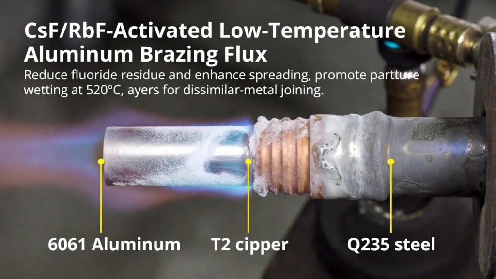
Aluminum and aluminum-alloy brazing in ambient atmospheres is fundamentally limited by the rapid formation of stable surface oxides. A high-activity fluoride-based flux is therefore essential to disrupt oxides, promote wetting, and enable reliable joints. Compared with conventional Nocolok-type fluxes (K3AlF6–KAlF4 / KAlF4) that typically operate near ~560–580 °C and often depend on controlled atmospheres, a CsF–AlF3 chemistry can lower the working temperature due to its reduced melting range. The flux system below further boosts wetting/spreading and supports dissimilar-metal brazing (“Al–steel”, “Al–Cu”) as well as “Al–Al” joints while keeping the melting range close to the filler melting window.
Target outcome (performance indicators): substantially increased flux and filler spreading on 6061 Al alloy, T2 copper, and Q235 steel at 520 °C, with strong joints in flame brazing (propane) around 500–600 °C and reduced flux consumption (lower post-braze fluoride residue load).
2) Detailed Experimental Procedure
2.1 Raw Materials and Formulation Window
Prepare a fluoride-based aluminum brazing flux with the following mass percentages:
- CsF: 46.0–54.0%
- Nano-Al(OH)3: 2.5–5.0% (100–200 nm)
- Nano-Al2O3: 2.5–5.0% (100–200 nm)
- Nano-RbF: 0.02–0.2% (100–200 nm)
- Nano-GaF3: 0.0001–0.0002% (100–200 nm)
- Nano-Ga2O3: 0.0001–0.0002% (100–200 nm)
- Balance: AlF3
Representative example compositions (mass %):
| Example | CsF | Nano-Al(OH)3 | Nano-Al2O3 | Nano-RbF | Nano-GaF3 | Nano-Ga2O3 | AlF3 (balance) |
|---|---|---|---|---|---|---|---|
| Example A | 46.0 | 5.0 | 2.5 | 0.2 | 0.0001 | 0.0002 | rest |
| Example B | 54.0 | 2.5 | 5.0 | 0.02 | 0.0002 | 0.0002 | rest |
| Example C | 50.0 | 3.5 | 3.0 | 0.1 | 0.0001 | 0.0001 | rest |
2.2 Powder Preparation and Mixing (Flux Manufacturing)
- Drying and moisture control: Keep all fluoride powders and nano-additives dry. Use sealed containers and low-humidity handling to prevent caking and activity loss.
- Particle size verification: Confirm nano-Al(OH)3, nano-Al2O3, nano-RbF, nano-GaF3, and nano-Ga2O3 are within 100–200 nm to maximize interfacial reactivity and dispersion.
- Weighing: Accurately weigh each component per the target mass percentages. For ultra-low Ga-based additions, use an analytical balance suitable for micro-quantities and prepare a pre-blend dilution if needed to improve dosing accuracy.
- Premix micro-additives: First blend nano-GaF3 + nano-Ga2O3 into a small portion of AlF3 (or CsF) to form a uniform master mix, minimizing local hotspots.
- Main blending: In a clean stainless-steel container, add CsF and AlF3, then introduce nano-Al(OH)3 and nano-Al2O3, followed by nano-RbF, and finally the Ga-based master mix. Mix until homogeneous.
- Deagglomeration: If nano powders form soft agglomerates, use gentle dry milling or sieving (without introducing moisture) to restore flowability and uniformity.
- Packaging: Store the finished flux in moisture-barrier packaging with tight sealing. Label with batch ID, composition, and handling precautions.
2.3 Melting Range and Process Window
The flux is designed to melt in the 448–462 °C range (typical), which is close to practical filler melting/flow conditions and supports robust wetting in dissimilar joints. This lower melting range also helps reduce thermal load on assemblies and widens workable brazing conditions for complex geometries.
2.4 Wetting/Spreading Test (R&D Characterization)
- Reference method: Conduct wettability/spreading evaluation following GB/T 11364-2008 conditions.
- Substrates: 6061 aluminum alloy plate, T2 copper plate, and Q235 steel plate. Prepare surfaces by degreasing and light abrasion as appropriate to remove contaminants and loosely bound oxides.
- Consumables: Use Zn85–Al15 filler. Typical masses per test: 100 mg filler and 15 mg flux.
- Thermal condition: Heat to 520 °C and hold long enough for flux melting, oxide disruption, and filler spreading to reach a stable area.
- Readout: Record flux spreading area and filler spreading area on each substrate; compare against a commercial CsAlF4-type flux baseline for benchmarking.
2.5 Flame Brazing Validation (Application Trial)
- Joint sets: Q235 steel + 6061 aluminum alloy, T2 copper + 6061 aluminum alloy, and 6061 + 6061 aluminum alloy.
- Flux application: Apply a controlled, thin flux layer to the faying surfaces and adjacent regions where filler flow is required. Aim for minimal but continuous coverage to reduce residue while maintaining oxide removal.
- Filler placement: Position Zn85–Al15 filler at the joint line. Ensure consistent gap control and fixturing to promote capillary flow.
- Heating: Use propane flame heating, typically within 500–600 °C at the joint region. Heat uniformly to activate the flux (melt) before driving filler flow.
- Cooling: Allow controlled cooling to reduce thermal shock and distortion, particularly in dissimilar joints.
- Post-braze cleaning: Remove fluoride residue using an appropriate cleaning method (selected based on part geometry and corrosion sensitivity) to prevent long-term corrosion or performance degradation.
3) Comparison vs Traditional Flux Routes (Summary)
- K-based Nocolok (KAlF4 / K3AlF6–KAlF4): cost-effective and widely used (e.g., radiator brazing), but typically higher melting/working temperatures and may require controlled atmospheres to maintain high activity.
- CsAlF4-type flux: lower melting point (around the mid-400 °C range), enabling easier brazing of aluminum alloys, but Cs-containing systems are expensive, limiting adoption when used at conventional dosages.
- ZnF2-containing flux variants: can deliver high activity for dissimilar joints, but ZnF2 is typically moisture-sensitive (hygroscopic), increasing storage/handling difficulty and risking caking and activity loss.
- High-Rb flux chemistries: may improve performance but often drive material cost too high for large-scale use.
This CsF–AlF3 system reinforced by nano-RbF and nano-oxide/hydroxide additives targets a practical balance: low melting range comparable to Cs-based low-temperature fluxes, substantially higher wetting/spreading, compatibility with Al–steel/Al–Cu/Al–Al brazing, and improved economics by reducing required flux usage (thereby lowering residue and total Cs consumption per joint).
4) Why CsF and RbF Matter Here (Advantages of CsF/RbF Compounds)
CsF as the primary activator: CsF is the core driver that pushes the flux chemistry toward a lower melting regime than K-based systems, enabling earlier activation, faster oxide disruption, and easier wetting at temperatures aligned with common aluminum brazing fillers. In CsF–AlF3 matrices, the molten fluoride phase can penetrate oxide films and enhance interfacial cleanliness, which is crucial for dissimilar joints where wetting is inherently more difficult.
Nano-RbF as a high-leverage promoter (even at 0.02–0.2%): RbF in nano form acts as a reactivity amplifier in the molten fluoride environment. At very low loading, nano-RbF helps improve flux/filler spreading and supports stable wetting on steel and copper surfaces while preserving the low-temperature advantage of CsF. Using RbF only as a micro-addition avoids the cost penalty of high-Rb formulations, yet retains performance gains where it counts: interfacial activation.
CsF + RbF synergy with AlF3 (the structural backbone): AlF3 provides the main matrix and fluoride chemistry stability. The CsF/RbF pair tunes molten-phase behavior (fluidity, wetting kinetics, and oxide interaction) without forcing higher melting behavior.
Practical manufacturing advantage for scale-up: This flux can be produced by controlled dry blending in stainless containers (no complex synthesis required), which is attractive for industrial deployment. For manufacturers, the key quality levers are (i) maintaining dryness, (ii) ensuring nano-additive dispersion, and (iii) controlling batch homogeneity—directly translating into consistent brazing performance.