Hollow-Core Photonic Crystal Fiber Rubidium Vapor Blue Laser (420 nm) for Underwater Optical Communication & Precision Metrology
1) Overview & Technical Value
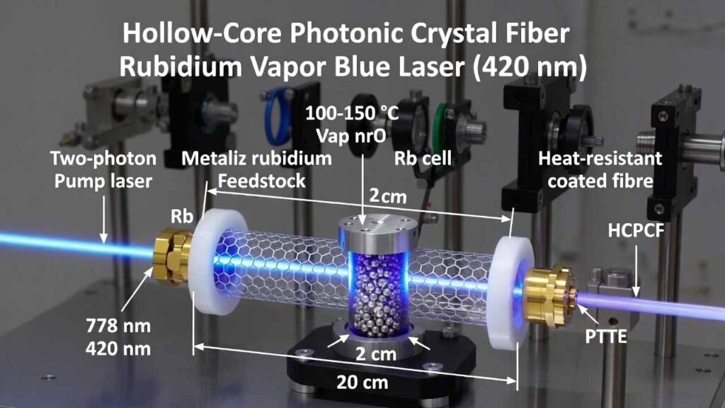
This configuration generates a narrow, directional 420 nm blue laser from rubidium (Rb) vapor by two-photon pumping at 778 nm inside a sealed vapor cell. A hollow-core photonic crystal fiber (HCPCF) is mounted inside the Rb cell and acts as an in-cell resonant/feedback and long-interaction structure: it extends the effective gain length and repeatedly guides the interacting wavelengths, helping the blue field build up into a stronger laser output.
Compared with free-space vapor-cell upconversion approaches, fiber-filled or fiber-assisted alkali-vapor platforms are attractive because they confine light tightly over a long path length, improving light–atom interaction strength while keeping the overall package compact and robust. This enables practical blue sources aimed at underwater optical communication, ocean sensing, high-density optical techniques, laser cooling/atomic physics tooling, and precision measurement/target illumination, where blue wavelengths offer favorable propagation and/or strong atomic transitions.
- 778 nm pump drives a two-photon excitation in hot Rb vapor.
- Population dynamics can produce mid-IR ASE around 5.23 μm and support stimulated emission that yields 420 nm blue output.
- HCPCF guides and amplifies the relevant wavelengths via multiple passes/reflections inside the fiber core, improving buildup and beam quality.
| Parameter | Typical Value / Range |
|---|---|
| Pump source | Diode laser or dye laser |
| Pump wavelength | 778 nm |
| Pump linewidth | < 0.3 cm-1 (example: ~0.25 cm-1) |
| Pump power | Example: 5–20 mW adjustable |
| Rb cell material | Quartz or K9 glass |
| Cell size (example) | 20 cm length, 2 cm diameter |
| Metallic Rb charge | Example: ~2 g (solid) |
| Operating temperature | 60–200 °C (often controlled around 100–150 °C) |
| Cell pressure spec | Sealed and evacuated; stated residual pressure window 0.1–10 kPa (example: ~6 kPa) |
| Fiber selection constraints | Designed to preferentially support 778 nm and 420 nm; zero-dispersion near 420 nm |
| Fiber coating | Heat-resistant silicone coating or metal coating |
| Fiber fixture | PTFE (Teflon) ring inside the cell |
| Focusing optic | Plano-convex lens, example f = 50/100/150 mm |
2) Detailed Experimental Procedure (Build → Seal → Run → Optimize)
Safety boundary: Metallic rubidium reacts aggressively with moisture and oxygen and can ignite. Use dry inert handling practices (e.g., glovebox or rigorously purged inert manifold), face/hand protection, and appropriate fire controls for alkali metals. Ensure your institution’s laser safety and hazardous-material SOPs are followed.
-
Prepare parts and metrology tools
- Rb vapor cell body (quartz or K9 glass) with one end prepared for lens mounting and vacuum connection/porting.
- HCPCF segment (straight-through or ring-coupled mounting style), with coating rated for your operating temperature and chemical environment.
- PTFE ring fixture sized to hold the HCPCF centered inside the cell.
- 778 nm pump source (diode or dye), with linewidth < 0.3 cm-1; power control; beam conditioning as needed.
- Plano-convex lens (choose focal length to match your cell geometry and desired fiber coupling).
- Diagnostics: optical power meter for 420 nm, spectrometer (verify 420 nm line and suppress ASE background), beam profiler if available, thermal sensors.
-
Clean and dry the optical/vacuum surfaces
- Clean cell windows and internal surfaces with compatible solvent protocol; fully dry.
- Dry-bake components if your process allows, focusing on reducing adsorbed water and organics.
- Keep parts in a dry inert environment after cleaning to prevent re-adsorption.
-
Install and fix the HCPCF inside the vapor cell
- Insert the HCPCF into the cell body and position it along the optical axis.
- Use the PTFE ring to fix the fiber mechanically inside the cell, ensuring stable centering and minimal stress.
- Confirm that the fiber routing supports the intended coupling approach (direct straight coupling or ring-style routing).
-
Load metallic rubidium (solid) into the cell
- In an inert environment, transfer a measured mass of metallic rubidium (example: ~2 g) into the cell reservoir region.
- Physically separate the Rb reservoir from the primary optical windows as your design permits, reducing risk of window fogging from condensed Rb.
-
Seal and evacuate the cell
- Connect the cell to a vacuum manifold; evacuate to the target residual-pressure specification (stated window: 0.1–10 kPa; example working point: ~6 kPa).
- Leak-check, then seal (valve closure and pinch-off/flame seal depending on your cell design).
- Record final pressure/processing conditions to support reproducibility across builds.
-
Integrate heating and temperature control
- Mount the cell in a controlled heater (band heater, oven, or film heater) with a stable temperature controller.
- Set operating temperature within 60–200 °C; many implementations stabilize around 100–150 °C to balance vapor density, output stability, and window cleanliness.
- Implement a thermal gradient strategy (keep windows slightly warmer than the reservoir path) to reduce rubidium condensation on optical surfaces.
-
Optical injection: focus 778 nm pump into the HCPCF
- Align the pump along the cell axis and mount the plano-convex lens with its convex surface facing the pump source.
- Focus the 778 nm beam into the HCPCF core inside the cell; maximize coupled power while monitoring back-reflections and stability.
- Use polarization control if needed to match your selected excitation pathway and maximize blue generation.
-
Initiate blue generation and tune for gain
- Ramp temperature to the setpoint and allow thermal equilibrium.
- Enable the pump and slowly increase power; monitor emerging 420 nm signal and spectrum.
- Iterate coupling alignment (lens position, beam pointing, focus) to maximize 420 nm output while maintaining stable pump transmission.
-
Optimization loop (practical knobs)
- Temperature: adjust within 60–200 °C to tune Rb vapor density and balance gain vs. absorption/line broadening.
- Coupling: fine-tune focus to maintain stable core coupling; the HCPCF’s guiding can reduce the need for external cavity optics.
- Fiber choice: use fiber designs that strongly support 778/420 nm guidance and are robust at your operating temperature.
- Pump quality: keep linewidth narrow and frequency stable around the targeted transition condition.
-
Output collection and characterization
- Separate the 420 nm output from residual 778 nm pump with appropriate dichroics/filters.
- Measure optical power, beam profile, and spectral purity; log long-term drift vs. temperature and pump detuning.
- For application integration, characterize divergence, pointing stability, and modulation response (if needed).
-
Shutdown and storage
- Reduce pump power to zero, then cool the cell in a controlled manner to avoid uncontrolled condensation patterns.
- Store the sealed module in a dry, temperature-stable environment; record run hours and any contamination events.
3) Comparison vs. Traditional Rubidium Blue-Light Upconversion (Summary)
A common route to rubidium blue output uses free-space excitation in a heated Rb cell and relies on phase-matched nonlinear processes (often described as four-wave mixing) to produce a 420 nm field. While effective, such setups frequently depend on careful optical alignment and can benefit from external resonant enhancement or specific buffer-gas strategies depending on the exact architecture and performance target.
The HCPCF-in-cell approach changes the engineering trade-offs by placing the resonant/interaction structure inside the rubidium environment:
- Longer effective interaction length: guided propagation in the hollow core increases light–Rb overlap over a long path.
- In-cell resonant behavior: repeated guidance/multiple-pass effects help the 420 nm field build up without a bulky external cavity.
- Reduced “optical-path tuning” burden: fewer free-space resonator optics can simplify packaging and improve robustness.
- Compact, lightweight module potential: the resonant element is the fiber, enabling small form-factor integration.
- Beam quality advantage: the guided mode exiting the HCPCF tends toward a near-circular, more uniform output profile, aiding downstream coupling.
4) Why Metallic Rubidium Is the Critical Feedstock (Performance + Manufacturability)
Using metallic rubidium (loaded as a solid charge) is not just a convenience—it is what makes the vapor-cell laser manufacturable, controllable, and repeatable. In this architecture, metallic Rb is the direct vapor source: when the sealed cell is heated, the metal establishes the rubidium vapor density that sets the optical depth, gain dynamics, and ultimately the 420 nm output level.
- Direct vapor-generation with no counter-ions: metallic Rb produces a clean atomic vapor environment without introducing anions or decomposition byproducts from salts/organometallic sources.
- Temperature-tunable vapor density: vapor pressure (and thus atomic density) is strongly temperature-dependent, giving a simple, high-resolution knob for power and stability optimization.
- Stable long-life reservoir: a properly sealed, dry cell allows the solid metal to act as a persistent vapor reservoir for long-term operation and repeatable startup behavior.
- Lower contamination risk for optics (when engineered correctly): by controlling thermal gradients and reservoir placement, you can reduce window fogging while maintaining high vapor density where the HCPCF interaction occurs.
- Scales to integrated modules: metallic Rb loading is compatible with compact sealed-cell fabrication workflows, supporting rugged blue sources for fieldable sensing/communication systems.