Miniature CPT Rubidium Vapor Magnetometer for Navigation, UAVs, and Medical Imaging
1) Overview and Technical Value
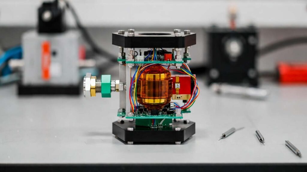
This device is a compact, opto-electronic coherent population trapping (CPT) magnetometer built around a sealed rubidium (Rb) atomic vapor cell. A dual-frequency coherent laser field is converted into circularly polarized light and sent through an Rb vapor interaction region; the transmitted (or reflected) optical power is detected by an integrated photodiode. When the two optical frequencies satisfy the CPT condition, the atomic population is driven into a “dark” superposition state and the optical response changes sharply. External magnetic fields shift the Zeeman sublevels and therefore move/split the CPT spectral features. By tracking these CPT resonance peak positions (e.g., three prominent peaks associated with Zeeman components under a defined optical geometry), the system calculates the magnetic-field magnitude with high sensitivity while keeping the overall package small, lightweight, and integration-friendly. This architecture targets applications that need precision magnetic sensing in tight volumes, such as attitude/navigation modules in autonomous systems, compact instrumentation in aircraft/satellites, and positioning/reconstruction support in medical magnetic imaging subsystems.
2) Detailed Experimental Procedure
- Define the three-cavity stack and optical interfaces. Lay out a stacked structure consisting of (i) a detection chamber with a photodiode, (ii) a rubidium atomic vapor chamber, and (iii) an optical cavity/beam-routing chamber. Include a glass window between detection and vapor chambers (same window dimensions to ensure optical continuity) and matched narrow slits between optical and vapor chambers (same slit dimensions to constrain beam geometry and reduce stray light).
- Prepare top and bottom sealing wafers. Use high-borosilicate glass as the top and bottom cover plates for hermetic sealing of all three chambers. Clean all glass surfaces using sequential solvent cleaning (e.g., alcohol rinse), deionized water rinse, and thorough drying. Finish with low-residue surface activation (e.g., UV-ozone or plasma) if available to improve bonding quality.
- Fabricate/assemble the chamber bodies. Implement the chamber bodies using micro-machined glass, silicon, or ceramic substrates depending on your process line. Maintain tight tolerances for the slit/window alignment so the optical axis passes from the laser cavity to the Rb vapor region and into the detector window without clipping.
- Install the photodetector in the detection cavity. Mount a low-noise photodiode (or photodiode + transimpedance amplifier on a small PCB) inside the detection chamber. Route electrical feedthroughs with low magnetic signature (short loops, symmetric routing) to avoid self-field offsets.
- Create the rubidium vapor cell using metallic rubidium as the feedstock. In an inert atmosphere (argon glovebox preferred), dose a precisely weighed micro-quantity of metallic rubidium into the vapor chamber or into a dedicated reservoir pocket connected to the vapor chamber. If a buffer-gas environment is required for linewidth and sensitivity optimization, backfill the cell with the selected buffer gas (or mixture) to a controlled pressure; otherwise evacuate to the required vacuum level. Seal the cell promptly after dosing to prevent oxidation/hydrolysis of the metal.
- Hermetically bond the device stack. Seal the chamber stack using a bonding method compatible with your substrates (e.g., glass-to-silicon anodic bonding or glass-to-glass bonding). Ensure the first high-borosilicate glass plate seals the top of the detection/vapor/optical cavities and the second high-borosilicate glass plate seals the bottom. Verify bonding integrity (visual inspection, leak test, optical transmission check through the windows).
- Build the optical chain in the optical cavity. Integrate the laser source (a VCSEL is commonly used for miniature atomic devices), a plano-convex collimating lens, a laser isolator to suppress back-reflections/stray light, a polarizer to generate linear polarization, a quarter-wave plate to convert to circular polarization, and a mirror to fold the path through the rubidium region. Mechanically constrain optics to survive vibration while preserving polarization purity.
-
Generate the dual-frequency coherent optical field.
Use one of the following approaches:
- Modulated single-wavelength VCSEL: modulate the injection current at a microwave frequency to create coherent sidebands; select operating conditions so the two first-order sidebands form the effective bichromatic field required for CPT.
- Dual-output/dual-wavelength source: directly generate two phase-coherent optical frequencies and combine them into the same spatial mode prior to the polarizer and quarter-wave plate.
- Align the beam path through slits/windows. Adjust the collimation and mirror angle so the circularly polarized bichromatic beam passes through the optical slit into the rubidium vapor chamber, interacts with the vapor, and exits through the matched glass window into the detection cavity. Confirm that the photodiode sees a stable baseline optical power with minimal clipping.
- Set rubidium vapor density by temperature control. Heat the rubidium vapor chamber to the operating temperature required for target optical depth and CPT contrast. In miniature cells, a typical working range is tens of degrees above ambient up to around ~75–100 °C, depending on cell volume, buffer gas, and desired linewidth. Keep heaters and current paths magnetically symmetric to prevent bias fields near the sensing volume.
- Acquire CPT spectra and extract magnetic field. Drive and scan the CPT condition (e.g., by sweeping the microwave modulation frequency or by controlled detuning while keeping optical alignment fixed) and record the photodiode signal versus scan parameter. Identify the CPT resonance features (often seen as distinct peaks/dips; in many compact implementations, three strong peaks can be resolved under suitable configuration). Calibrate the relationship between the measured resonance splitting/shift and magnetic-field magnitude using a known reference field (e.g., Helmholtz coil). During operation, convert real-time peak positions into the external magnetic-field value using the calibration model.
- Packaging, shielding, and validation. Add magnetic shielding only if the use-case allows (shielding improves stability but adds size). Validate sensitivity, bandwidth, heading error (if relevant), temperature drift, and long-term stability. Record the required laser power, heater power, and signal-to-noise performance for system-level integration.
Safety note for lab execution: metallic rubidium is highly reactive with oxygen and moisture. Dosing, transfer, and sealing must be performed under inert conditions with appropriate PPE and rigorously dried components.
3) Summary Comparison: This Production Approach vs Traditional Approaches
Compared with traditional bench-top atomic magnetometer builds (discrete glass-blown cells, free-space optics on mounts, and bulky enclosures), the integrated three-cavity stack with borosilicate sealing compresses optics + vapor interaction + detection into a single miniature module. The aligned slits/windows force a controlled optical path, reducing alignment degrees of freedom and making the design more manufacturable and repeatable. Relative to common non-atomic magnetometers, the CPT Rb-vapor method avoids cryogenics (unlike SQUID systems), can be made far smaller than many fluxgate assemblies for similar low-field resolution targets, and supports scalable integration with VCSEL-based photonics. The main manufacturing challenge shifts from “optical bench alignment” to “clean sealing + alkali handling + low-magnetic packaging,” which is typically more compatible with batch processes and productization once the sealing and dosing steps are stabilized.
| Dimension | Integrated CPT Rb-Vapor Module | Traditional Implementation (Typical) |
|---|---|---|
| Optical layout | Fixed by cavities, matched slits/windows, fewer alignment variables | Manual alignment of mounts/optics, higher assembly variability |
| Form factor | Chip-/module-scale, easy to embed | Larger enclosures or optical benches |
| Cost drivers | Sealing yield, alkali dosing, low-magnetic packaging | Labor-heavy alignment, bulky optics/mechanics |
| Scalability | More compatible with batch/wafer-level processes | Lower throughput, unit-to-unit variability |
4) Why Metallic Rubidium is the Key Material (and Its Advantages Here)
The sensing mechanism depends on a stable, controllable density of rubidium atoms in the vapor phase. Metallic rubidium is the most direct and controllable feedstock for generating that vapor inside a sealed cell: once dosed and hermetically sealed, the metal establishes an equilibrium vapor pressure governed by temperature, enabling repeatable tuning of optical depth and CPT contrast. For miniature CPT magnetometers, metallic Rb also aligns naturally with VCSEL-based photonics because rubidium’s D-line transitions sit in laser-friendly near-IR wavelengths used widely in compact atomic devices. In manufacturing terms, using metallic rubidium allows precise control of the total alkali inventory (important for lifetime and drift), supports small “excess metal” strategies to maintain an alkali-rich environment over time, and avoids introducing counter-ions or decomposition byproducts that can broaden resonances or contaminate optics.
- Direct vapor generation: metal-to-vapor equilibrium enables straightforward temperature-based control of atomic density without extra chemistry inside the sensing volume.
- High signal potential in a tiny cell: with correct dosing and temperature setpoint, metallic Rb supplies enough vapor pressure to reach strong CPT contrast even in micro-scale cavities.
- Cleaner atomic environment (when sealed correctly): avoiding salts/precursors reduces the risk of residual fragments that can increase optical loss, add background absorption, or destabilize resonance features.
- Lifecycle and stability leverage: accurate metallic dosing supports tighter device-to-device matching and long-term drift control in navigation-grade or instrumentation-grade builds.
- Process discipline advantage: because metallic Rb is highly reactive, it forces best-practice dry processing (low moisture/oxygen, clean bonding, controlled backfill), which directly improves vapor-cell quality and magnetometer repeatability.