Rubidium Carbonate–Enabled Low-Temperature LFP Cathode Materials for Power Batteries and Extreme-Climate Energy Systems
1) Overview
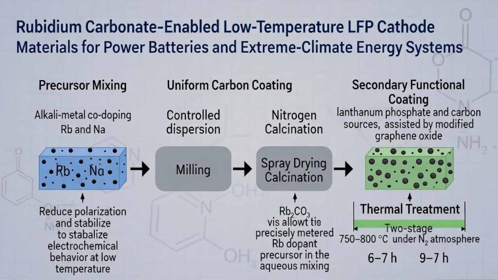
Low-temperature performance is a major bottleneck for lithium iron phosphate (LFP) cathodes, especially in high-latitude, high-altitude, and polar environments where cells may be stored and operated well below freezing. A practical route to improve cold-start discharge capacity, voltage stability, and long-cycle retention is to combine:
- Alkali-metal co-doping (Rb and Na) during precursor mixing to reduce polarization and stabilize electrochemical behavior at low temperature.
- Uniform carbon coating formed through controlled dispersion, milling, spray drying, and nitrogen calcination.
- Secondary functional coating using lanthanum phosphate and carbon sources, assisted by modified graphene oxide for better compatibility and dispersion.
Rb₂CO₃ (rubidium carbonate)
Used as a precisely metered Rb dopant precursor in the aqueous mixing stage.
Stage 1: 750–800 °C, 6–7 h
Stage 2: 750–800 °C, 9–10 h
2) Detailed Experimental Process
Process objective: produce a low-temperature-resistant LFP cathode powder via (i) Rb/Na co-doping and carbon coating, then (ii) lanthanum phosphate + carbon secondary coating aided by modified graphene oxide.
Step A — Prepare doped, carbon-coated LFP intermediate
-
Prepare aqueous binder/surfactant medium
Add 0.12–0.15 parts polyurethane resin and 0.04–0.06 parts surfactant into 10 parts water. Stir until uniform.- Polyurethane resin: water-soluble type (example condition used: ~30 wt% solids; viscosity in the 60–85 cps range).
- Surfactant blend (mass ratio): polysorbate : alkylphenol polyoxyethylene ether : modified allyl alcohol polyoxyethylene ether = 2–3 : 1 : 0.4–0.7.
-
Introduce inorganic precursors (doping + lithium source)
Under continuous stirring, add:- 1 part anhydrous iron phosphate (FePO₄)
- 0.20–0.24 parts lithium carbonate (Li₂CO₃)
- 0.03–0.04 parts rubidium carbonate (Rb₂CO₃)
- 0.01–0.02 parts sodium carbonate (Na₂CO₃)
-
Fine milling for controlled particle size
Mill Mixture A until D50 = 0.2–0.3 μm to improve mixing uniformity and enable consistent spray drying and coating formation. -
Spray drying
Spray-dry the milled slurry to obtain Powder A. -
Nitrogen calcination (Stage 1)
Calcine Powder A under N₂ at 750–800 °C for 6–7 h to obtain Rb/Na-doped, carbon-coated LFP intermediate.
Step B — Secondary coating with lanthanum phosphate + carbon, assisted by modified graphene oxide
-
Form secondary-coating slurry (Mixture B)
Mix the Stage-1 intermediate with the following (mass ratio shown):- Intermediate : LaPO₄ : glucose : modified graphene oxide : water
- 1 : 0.03–0.04 : 0.03–0.04 : 0.01–0.02 : 10–15
-
Fine milling (again) for coating uniformity
Mill Mixture B to D50 = 0.2–0.3 μm. -
Spray drying (again)
Spray-dry the milled slurry to obtain Powder B. -
Nitrogen calcination (Stage 2)
Calcine Powder B under N₂ at 750–800 °C for 9–10 h to obtain the final low-temperature-resistant LFP cathode material.
Auxiliary preparations (materials compatibility and dispersion)
1) Modified allyl alcohol polyoxyethylene ether (surfactant component)
- Blend 30–35 parts Si–H-terminated polysiloxane with 7–10 parts allyl alcohol polyoxyethylene ether.
- Heat to 80–100 °C and stir for 50–60 min.
- Add 3–5 parts chloroplatinic acid and 5–6 parts 2,3-dimethyl maleic anhydride; mix well.
- React at 85–90 °C for 3–5 h, cool to room temperature to obtain the modified ether.
2) Modified graphene oxide (for improved compatibility)
- Amination: mix 1 part graphene oxide with 17–19 parts 18–20 wt% ammonia water; stir at 30 °C for 10–15 h, then at 65 °C for 10–14 h. Filter, wash, vacuum-dry to obtain aminated graphene oxide.
- Further modification: combine 1 part aminated graphene oxide with 1.3–1.4 parts 3,5-diethyl-2,4-toluenediamine, 7–8 parts 50 wt% isopropanol aqueous solution, and 2–3 parts 2.5 mol/L HCl aqueous solution. At 0 °C, add 4–5 parts 0.7 mol/L ammonium persulfate solution dropwise; stir for 9–10 h. Filter, wash, vacuum-dry to obtain the modified graphene oxide.
Practical material window referenced: graphene oxide sheet size around 0.4–0.8 μm supports dispersion and coating uniformity.
3) Comparison Summary: This Route vs. Conventional LFP Manufacturing
Conventional approach (typical industry baseline)
- Single-step carbon coating without targeted alkali-metal co-doping.
- Use of off-the-shelf surfactants that may not disperse the full slurry system effectively.
- No secondary phosphate coating or use of unmodified graphene oxide, often causing poor compatibility and non-uniform coverage.
- Higher risk of polarization increase and capacity/voltage drop after cold storage, plus weaker low-temperature cycling stability.
This route (Rb₂CO₃ + Na₂CO₃ co-doping + engineered dispersion + dual coating)
- Rb/Na co-doping is built into the aqueous precursor stage, improving dopant homogeneity and repeatability after milling and spray drying.
- Two-stage N₂ calcination supports formation of a robust carbon-coated doped LFP core, then a more uniform secondary layer.
- Lanthanum phosphate + carbon secondary coating improves interfacial behavior and low-temperature cycling stability.
- Modified graphene oxide enhances compatibility/dispersion, helping achieve more uniform coating density and coverage compared with unmodified GO.
- Expected electrochemical outcome (as described for this formulation): better discharge performance after low-temperature storage and higher mid-voltage during low-temperature discharge.
4) Why Rubidium Carbonate Matters Here: Advantages as a Rubidium Source
In this low-temperature LFP formulation, rubidium carbonate (Rb₂CO₃) is not a minor additive—it is the primary rubidium dopant precursor that enables controlled introduction of Rb into the cathode system during the earliest dispersion stage. That placement is critical for dopant uniformity and downstream coating quality.
-
Precise, repeatable Rb dosing in an aqueous workflow
The process adds 0.03–0.04 parts Rb₂CO₃ directly into the stirred water-based mixture, then locks in homogeneity via fine milling (D50 0.2–0.3 μm) and spray drying—key for scale-up consistency. -
Synergistic co-doping with Na
Rb₂CO₃ is paired with Na₂CO₃; this co-doping strategy is described as improving low-temperature discharge behavior, likely by reducing lattice/electrode polarization effects and supporting charge-transfer at low temperature. -
Supports coating uniformity indirectly
When dopant distribution is uniform, subsequent carbon formation and secondary coating (LaPO₄ + carbon) are easier to make continuous and dense, which is essential for low-temperature cycling stability. -
Cleaner dopant precursor choice for cathode synthesis
Carbonate-based alkali sources are widely compatible with spray-drying and calcination routes; they integrate naturally into carbonate/lithiation workflows while avoiding introducing halide species into the precursor slurry. -
Manufacturing note for R&D and scale-up
For best repeatability in this process, use battery-grade Rb₂CO₃ with controlled moisture and trace-metal content, and keep raw-material handling consistent to maintain the targeted dopant window.
If your goal is to reproduce the cold-storage recovery and low-temperature voltage behavior described for this formulation, treat Rb₂CO₃ as a critical quality input: dosing accuracy, batch-to-batch purity consistency, and moisture control directly influence dopant effectiveness and coating uniformity. The synthesis method mentioned in this article references patent document number CN202410128235.2