Rubidium Carbonate (Rb₂CO₃) Bilayer Interfacial Engineering for High-Performance Perovskite Solar Cells
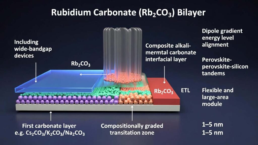
Application focus: perovskite solar cells (wide-bandgap devices, perovskite–silicon tandems, flexible and large-area modules) using a composite alkali-metal carbonate interfacial layer with rubidium carbonate near the electron-transport side.
1) Overview
Interfacial control between the perovskite absorber and the electron transport layer (ETL) is a primary lever for improving energy-level matching, defect passivation, open-circuit voltage (VOC), fill factor (FF), and operational stability in perovskite photovoltaics. Conventional carbonate interface modifiers often need to be extremely thin (typically <~2 nm) to avoid insulating behavior that can hinder electron extraction.
This process builds a bilayer alkali-metal carbonate interfacial stack with a compositionally graded transition zone: a first carbonate layer is placed adjacent to the perovskite (e.g., Cs2CO3/K2CO3/Na2CO3), while a second carbonate layer is placed adjacent to the ETL and can be rubidium carbonate (Rb2CO3). By continuously cross-ramping evaporation rates, the interface dipole changes gradually through thickness, enabling a total interlayer thickness of 1–5 nm while preserving strong charge transport and integrated interface functionality.
2) Detailed Experimental Process
| Item | Recommended range / definition | Why it matters to device physics |
|---|---|---|
| Total composite carbonate thickness | 1–5 nm | Thicker than typical “ultra-thin-only” carbonate layers, while maintaining charge transport and interface integration. |
| First carbonate layer thickness (perovskite side) | 0.5–3 nm | Provides strong surface dipole formation and defect passivation near perovskite without excessive blocking. |
| Thickness ratio (first : second) | 1:1 to 5:1 | Lets the perovskite-side carbonate dominate passivation/dipole control while ensuring ETL-side alignment is effective. |
| Transition zone | 5%–30% of total thickness, containing both carbonate components | Creates a smooth composition and dipole gradient, reducing abrupt potential steps that form transport barriers. |
| Second carbonate (ETL side) | Rb2CO3 (or K2CO3/Na2CO3) | Rb2CO3 supports ETL-side energy-level coupling, promotes efficient electron extraction, and strengthens the graded-dipole architecture. |
A. Device stack example (wide-bandgap perovskite cell)
-
Substrate preparation
Use patterned ITO glass. Ultrasonically clean in acetone, isopropanol, and ethanol for 10 min each. Dry with nitrogen. -
Hole-transport layer (HTL) deposition
Spin-coat a self-assembled small-molecule HTL at 4000 rpm for 30 s, then anneal at 100°C for 10 min. -
Perovskite absorber formation (wide bandgap)
Spin-coat perovskite with composition Cs0.05MA0.15FA0.8PbI2.25Br0.75 (bandgap ~1.68 eV).
Prepare precursor at 1.4 M in DMF:DMSO = 4:1. During spin coating, apply antisolvent in a staged drip. Anneal at 100°C for 30 min.
B. Composite carbonate interfacial layer via vacuum thermal evaporation (key step)
The composite interlayer is deposited between the perovskite absorber and ETL using vacuum thermal evaporation. The process relies on dynamic cross-ramping of two carbonate sources to build a graded transition zone and a stepwise dipole profile.
-
Set evaporation environment
- Chamber pressure: 5×10⁻⁴ Pa to 1×10⁻³ Pa
- Heating source: resistive heating boat (e.g., tungsten boat / quartz boat)
- Substrate rotation: keep perovskite-coated substrate rotating at 10–30 rpm
- Substrate temperature during deposition: 30–60°C
- Rate monitoring: use a quartz crystal microbalance (QCM) for real-time Å/s control
-
Deposit the first alkali-metal carbonate layer (perovskite side)
- Material options: Cs2CO3, K2CO3, or Na2CO3
- Typical heating windows (to enable stable evaporation behavior):
- Cs2CO3: 350–380°C
- K2CO3: 320–340°C
- Na2CO3: 270–310°C
- Initial deposition rate: 0.05–0.15 Å/s
- Target thickness: 0.5–3.0 nm
-
Build the graded transition zone (first carbonate → rubidium carbonate)
Use a four-stage cross-ramp strategy so the first carbonate decays while Rb2CO3 rises, creating a mixed-composition region.Stage First carbonate rate Rb2CO3 rate Time window Outcome 1 Ramp from 0.05–0.15 to 0.02–0.04 Å/s Off (0) 5–30 s Softens the first-layer growth to avoid abrupt termination. 2 Ramp from 0.02–0.04 to 0 Å/s Off (0) 5–30 s Ends first carbonate smoothly (no sharp boundary). 3 Off (0) Ramp from 0 to 0.06–0.08 Å/s 5–30 s Initiates Rb2CO3 growth gently to co-form the mixed transition zone. 4 Off (0) Ramp to and stabilize at 0.05–0.15 Å/s 5–30 s Completes the graded region and prepares for the main Rb2CO3 layer deposition. Set the transition-zone thickness to 5%–30% of the total composite interlayer thickness to balance dipole grading and transport continuity.
-
Deposit the second alkali-metal carbonate layer (ETL side): rubidium carbonate
- Material: Rb2CO3
- Deposition rate (main layer): typically within 0.05–0.15 Å/s
- Set thickness so the total composite carbonate thickness remains within 1–5 nm
-
Deposit ETL, buffer, and top electrode
- ETL: evaporate C60, thickness 20 nm, evaporation temperature ~450°C, rate 0.5 Å/s
- Buffer: deposit SnO2 by ALD, thickness 20 nm, deposition temperature 100°C
- Top electrode: evaporate Ag, thickness 100 nm, rate 1 Å/s
- Encapsulation: package the device in an inert atmosphere
C. Practical rate schedule example (Cs2CO3 → Rb2CO3)
- Evaporate Cs2CO3 at 0.1 Å/s, then ramp down to 0.04 Å/s over 15 s to form ~1 nm first layer.
- Continue ramping Cs2CO3 from 0.04 Å/s to 0 over 10 s.
- Start Rb2CO3: ramp from 0 to 0.06 Å/s over 10 s to build the mixed transition region.
- Ramp Rb2CO3 to 0.08 Å/s over 15 s, then continue to deposit ~1.0–1.5 nm second layer.
3) Comparison vs. Traditional Interfacial Approaches
- Typical constraint: carbonate layers are kept at ~≤2 nm to avoid insulating effects.
- Observed limitation: when thickness rises beyond ~2 nm, electron injection/extraction can be hindered, causing losses in JSC and FF.
- Result: hard to simultaneously satisfy defect passivation, dipole tuning, ion-migration suppression, and mechanical/stack compatibility in demanding device formats.
- Process: deposit carbonate A, stop; deposit carbonate B, start at target rate immediately.
- Issue: a distinct material boundary can introduce abrupt potential/energy-level discontinuities, forming local barriers and reducing charge extraction efficiency.
- Performance trend: devices with a graded transition zone show stronger VOC/FF synergy than “hard-interface” bilayers.
- Key difference: cross-ramped evaporation creates a compositionally continuous transition zone.
- Impact: smoother potential profile and dipole distribution improves transport continuity and lowers interfacial recombination probability.
- Representative device gains (example): PCE increased from 20.13% (no composite interlayer) to 21.98% with the composite carbonate layer; VOC reached 1.242 V, JSC 21.13 mA/cm², FF 83.75%.
4) Why Rubidium Carbonate (Rb₂CO₃) Is Advantageous in This Application
In the bilayer architecture, Rb2CO3 is placed on the ETL-adjacent side, where it plays a direct role in refining the interfacial electronic landscape between the perovskite and electron-transport material. Within a graded transition design, rubidium carbonate becomes more than a “thin modifier”: it becomes a controllable component of a dipole-gradient interfacial system.
- Energy-level coupling near the ETL: the Rb2CO3 side is used to further tune the perovskite/ETL alignment, supporting efficient electron extraction.
- Charge-transport continuity at practical thickness: with a graded transition zone, the composite interface can reach 1–5 nm total thickness while maintaining strong transport behavior, relaxing the usual “must be <2 nm” limitation.
- Interface defect passivation and recombination suppression: the carbonate bilayer structure reduces interfacial trap density and helps lower non-radiative recombination losses (reflected in improved VOC and FF trends).
- Ion-migration and stability support: the structured carbonate region provides an interfacial control zone that helps address stability-sensitive formats such as perovskite–silicon tandems, flexible devices, and large-area modules.
- Process controllability for R&D and scale-up: vacuum evaporation with QCM-controlled cross-ramping enables reproducible Å/s-level control, making the Rb2CO3 layer thickness and gradient formation highly tunable.
Materials note for engineers: because this application relies on Å/s-level rate control and nm-scale thickness precision, using high-purity, low-moisture Rb2CO3 helps maintain stable evaporation behavior and reduces the risk of process drift during transition-zone formation.
Summary takeaway: placing rubidium carbonate (Rb2CO3) as the ETL-side carbonate in a graded bilayer interfacial layer enables a thicker-yet-transport-friendly (1–5 nm) interface that boosts VOC and FF simultaneously while improving overall perovskite solar-cell performance and robustness. The synthesis method mentioned in this article references patent document number CN202510452055.4