Rubidium Fluoride (RbF)–Assisted Lead-Free Sn-Ag-Cu-Bi-Sb-Ni Solder Alloy Preparation for Electronics Joining
1) Overview and Technical Value
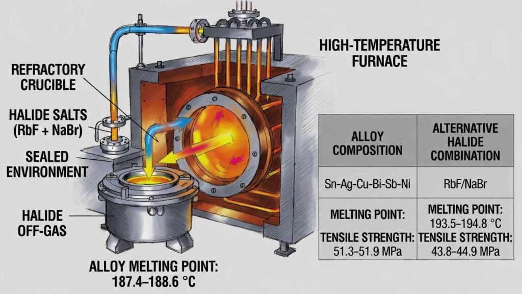
This workflow produces a lead-free tin-based multi-element solder alloy (Sn-Ag-Cu-Bi-Sb-Ni) designed for stable melting behavior and improved joint reliability. The core technical lever is introducing rubidium fluoride (RbF) together with sodium bromide (NaBr) during a sealed, high-temperature melt. Under sealed conditions, the halide additives generate a reactive halide-rich atmosphere that improves element compatibility during alloying, helping deliver a lower and more consistent melting point and higher tensile strength compared with non-matching halide systems.
- Melting point: ~187.4–188.6 °C
- Tensile strength: ~51.3–51.9 MPa
- Melting point: ~193.5–194.8 °C
- Tensile strength: ~43.8–44.9 MPa
Note: Processing temperatures listed below follow the provided specification (1480–1520 °C). Use appropriate refractory/crucible materials, sealed high-temperature furnace capability, and halide off-gas handling.
2) Detailed Experimental Procedure
- Metals: Sn, Ag, Cu, Bi, Sb, Ni (powdered prior to melting)
- Halide additives: RbF, NaBr
- Cleaning solvent: anhydrous ethanol
Target mass ratio (by weight)
| Component | Mass ratio range | Purpose in the workflow |
|---|---|---|
| Sn | 80–85 | Base solder matrix |
| Ag | 4–5 | Strengthening; solder performance tuning |
| Cu | 4–5 | Intermetallic control; joint reinforcement |
| Bi | 0.9–1.1 | Melting point reduction; microstructure tuning |
| Sb | 0.9–1.1 | Strength/stability improvement |
| Ni | 0.9–1.1 | Intermetallic modification; mechanical stability |
| RbF | 10–12 | Halide-vapor assisted alloying; compatibility and melting stability |
| NaBr | 10–12 | Works with RbF to form the process atmosphere; assists fusion and later degassing |
Step-by-step process
-
Powder preparation
- Ball-mill Sn, Ag, Cu, Bi, Sb, Ni into powders.
- Sieve to control particle size: ≤ 1 mm.
- Blend powders thoroughly in a mixing vessel: 120–150 rpm for 30–45 min to obtain a uniform mixed metal powder.
-
Ethanol cleaning (optional but recommended)
- Soak the mixed metal powder in anhydrous ethanol for 10–15 min.
- Stir during soaking to enhance cleaning and reduce entrained impurities.
- Filter and dry/remove solvent before charging into the furnace.
-
Sealed halide-vapor assisted melting and alloying
- Charge the cleaned mixed metal powder into the melting furnace/crucible.
- Add RbF and NaBr according to the selected ratio.
- Seal the furnace (close feed/discharge ports) and heat to 1480–1520 °C.
- Hold at temperature for 60–90 min under sealed conditions to promote alloying in the halide-rich atmosphere.
-
Controlled depressurization and degassing hold
- Cancel the sealed state (open the furnace to non-sealed condition) and allow natural pressure release.
- Maintain 1480–1520 °C for an additional 15–20 min to let halide gases exit the melt.
- Stir during this stage (typical guidance: 10–15 rpm) to improve gas removal and melt homogeneity.
- Obtain a uniform alloy melt.
-
Casting and cooling
- Pour the alloy melt into a mold.
- Cool to room temperature at a controlled rate of 10–20 °C/min to reduce cracking risk and stabilize properties.
- Demold to obtain the Sn-Ag-Cu-Bi-Sb-Ni alloy ingot (or proceed to downstream wire production as needed).
- Example A: Sn 80 kg, Ag 4 kg, Cu 4 kg, Bi 0.9 kg, Sb 0.9 kg, Ni 0.9 kg, RbF 10 kg, NaBr 10 kg; sealed melt 1480 °C/60 min; degas 1480 °C/15 min; cool 10 °C/min.
- Example B: Sn 82.5 kg, Ag 4.5 kg, Cu 4.5 kg, Bi 1.0 kg, Sb 1.0 kg, Ni 1.0 kg, RbF 11 kg, NaBr 11 kg; sealed melt 1500 °C/75 min; degas 1500 °C/17.5 min; cool 15 °C/min.
- Example C: Sn 85 kg, Ag 5 kg, Cu 5 kg, Bi 1.1 kg, Sb 1.1 kg, Ni 1.1 kg, RbF 12 kg, NaBr 12 kg; sealed melt 1520 °C/90 min; degas 1520 °C/20 min; cool 20 °C/min.
3) Comparison vs. Conventional/Alternative Approaches
Traditional Sn-based solder systems often relied on Pb to reduce melting point and simplify processing, but lead-free compliance requires alternative routes to achieve low, stable melting behavior and strong joints. In this process, the RbF + NaBr sealed-atmosphere stage is the differentiator versus approaches that use other salts or omit the matched halide atmosphere.
| Item | RbF + NaBr sealed-atmosphere alloying | Alternative salt combinations (examples) |
|---|---|---|
| Alloying compatibility | Enhanced mixing/compatibility of Sn/Ag/Cu/Bi/Sb/Ni during melting | Reduced compatibility when the matched halide atmosphere is disrupted |
| Melting point stability | Lower melting point with reduced fluctuation | Higher melting point and weaker stability trend |
| Mechanical strength | Higher tensile strength trend (about 51–52 MPa) | Lower tensile strength trend (about 44–45 MPa) |
| Impurity/gas management | Dedicated unsealing + high-temp hold helps drive halide gases out of the melt | Less effective atmosphere design and/or residual impacts possible |
Measured results summary (DSC melting point + tensile test)
| Sample | Salt system during melting | Melting point (°C) | Tensile strength (MPa) |
|---|---|---|---|
| Example 1 | RbF + NaBr | 188.6 | 51.3 |
| Example 2 | RbF + NaBr | 187.4 | 51.9 |
| Example 3 | RbF + NaBr | 188.1 | 51.7 |
| Comparative 1 | NaCl + NaBr | 193.5 | 44.5 |
| Comparative 2 | RbF + Na2SO4 | 194.3 | 44.9 |
| Comparative 3 | NaCl + Na2SO4 | 194.8 | 43.8 |
4) Why Rubidium Fluoride (RbF) Is Superior in This Application
In this lead-free solder alloying route, RbF is not a minor additive; it is a functional raw material that enables the process atmosphere and drives the property gains. Based on the described mechanism and comparative results, the key advantages of using RbF are:
- Halide-vapor assisted alloying: Under sealed heating, RbF (with NaBr) contributes to a halide-rich atmosphere that promotes fusion and improves compatibility among Sn, Ag, Cu, Bi, Sb, and Ni, supporting a more uniform alloy.
- More stable low-melting behavior: The RbF-enabled atmosphere correlates with a lower melting point range (~187–189 °C) compared with alternative salt systems (~193–195 °C), which is valuable for solder processing windows and repeatability.
- Higher joint reliability potential via strength increase: The RbF + NaBr route shows higher tensile strength (~51–52 MPa), which can translate to improved crack resistance at solder joints under mechanical/thermal stress.
- Cleaner final alloy through designed degassing: The workflow explicitly switches from sealed to unsealed and holds at temperature with stirring to drive halide gases out, reducing the likelihood that residual gas-phase species degrade alloy performance.
- Process robustness for engineering scale-up: With defined ratios, temperature windows, hold times, and cooling rates, RbF becomes a controllable “process atmosphere reagent,” helping engineers tune melting stability and mechanical outcomes without relying on lead.
- Use corrosion-resistant, high-temperature-compatible furnace internals and crucibles suitable for halide exposure.
- Ensure sealed-operation integrity during the first hold and controlled venting during the degassing hold.
- Provide proper off-gas capture/scrubbing and ventilation for halide vapors.
- Validate final composition and residual halide content per your QA plan (e.g., O/N/H, halide residues, microstructure, wetting tests).